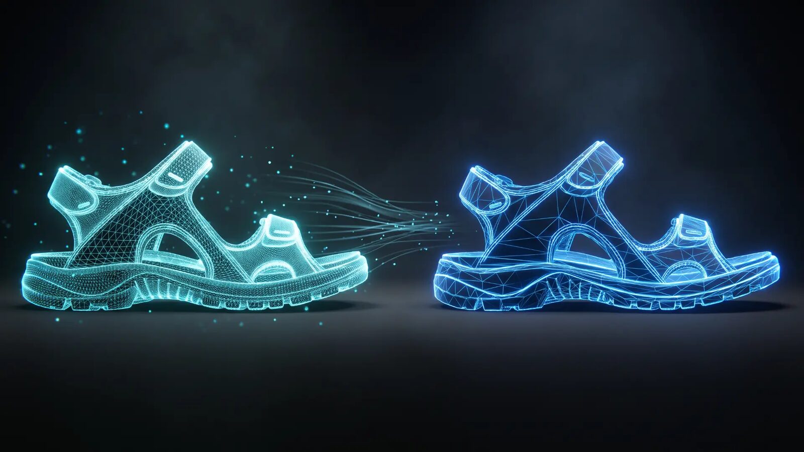
Mesh reduction and texture reduction are the part that already works. Getting the geometry and the material to arrive in the same place, as one production real time ready asset, is the part that usually breaks.
Quick answer
CAD and production data carry far more geometry and texture resolution than a real time editor, a web shop or a configurator can handle. Optimization solves that with mesh reduction and PBR texture reduction, targeted at the application the asset is headed for rather than at a generic polygon budget. What usually goes wrong is not the reduction itself. It is that geometry and material get assembled by hand at the far end of the pipeline, so the lightweight model quietly stops matching the product it was built from.
Production data was never built to be looked at
If your 3D team spends more time preparing a model than working with it, that is not a workflow you configured badly. It is the gap between two jobs that happen to share a file.
A Rhino model, a CAD assembly, a scanned last, a full resolution material set: all of these exist to describe how something gets manufactured. Every trimmed surface and every 8K map is there because production needs that precision. Then the same data has to run somewhere else entirely. In a browser. In a real time editor. In a configurator a customer opens on a phone on the train.
Those environments have hard limits. A configurator has a load budget measured in seconds, a real time editor one measured in frames. Nothing about production geometry respects either. So the model gets translated by hand: tessellate, decimate, retopologize, bake, resize, export, test, and start over when it looks wrong. Nobody in that loop is slow. They are doing a second job that was never scheduled.
The reduction is the part that already works
Mesh reduction and texture reduction are mature engineering problems. Given a target, they are deterministic, automatable and repeatable. Polycount, draw calls, file size, load time: every one of them is measurable, so you can prove afterwards that the asset hit its target.
The target matters more than the ratio. A web shop, a product configurator, a real time editor and an XR viewer all tolerate different budgets, and reducing to the specific final application beats reducing to a generic rule of thumb every time.
Which leaves the question worth asking: if the reduction is solvable, why do optimized models so often come back looking not quite like the product?
Metal buckle
What actually drifts is the appearance
Geometry has units. Appearance, in most pipelines, does not.
You can demonstrate that a mesh hit its polygon target. Nobody logs the moment a base color map got nudged half a step warmer during a bake, on a display nobody had calibrated, under office light, late in the day. It looked right at that moment. It usually did.
The structural problem is that geometry and material rarely arrive from the same place. A CAD file brings precise surfaces and no usable material data at all. A model built in a 3D application brings textures that were authored elsewhere, under someone else's viewing conditions. Somebody has to put the two together, and that assembly tends to happen by hand, late, on whatever screen is available.
That matters more at the end of the pipeline than at the start. A material reference inside a development file still gets checked against the physical sample. A material on a configurator is what someone buys against.
None of this is anyone's mistake. The intent was right at the beginning and reasonable at every single step. It simply was not carried.
DMIx AppLink to RapidPipeline: where geometry and material come together
The fix is not a better decimation algorithm. It is a single place where the two halves of the asset arrive together and leave as one production ready model.
That is what the DMIx AppLink to RapidPipeline is for. AppLink is the API driven way DMIx connects external applications, and RapidPipeline is a specialist platform for CAD data prep and 3D asset optimization. On import into DMIx you can run the RapidPipeline workflow and optimize formats and data volume for the application the asset is headed for:
- CAD import and tessellation. A CAD model is a surface description, not a polygon mesh. On import it is tessellated into a mesh, and the UVs that mesh needs are generated, which is what makes a material applicable at all. Automatically generated UVs are a solid starting point rather than a finished layout, and complex parts can still need manual work afterwards.
- Mesh reduction. Geometry complexity is brought down to what real time and web based applications can carry, sized to the final use case rather than to a generic budget.
- PBR texture reduction. Where a model arrives with textures already authored elsewhere, those texture sets come in with it and are reduced alongside the geometry, down to a footprint a browser or a real time editor can load, while the maps stay physically based.
- Where the material joins the model. A CAD file carries no usable material data, so the material is added in DMIx from the library. It stays connected to its master data, article number and supplier, so the lightweight asset points at a material that can actually be ordered.
- Onward use. From there the asset moves on to real time editors, web shops and configurators, without another manual preparation round. The optimized model can also be viewed and worked with directly in DMIx.
Underneath the mechanics sits the principle that governs everything in DMIx: one standard, with material specific tolerances around it. Color data in the library is spectrally measured, which means the color itself rather than its appearance on a particular screen. A model that got lighter is fine. A second version of the truth is not.
Next steps
Explore RapidPipeline in DMIx. Want to run the optimization step on one of your own CAD models? Talk to us directly: we take 30 minutes, on your data.
Learn more about RapidPipeline:

Frequently asked questions
- Can CAD data be used directly in a web shop or a configurator?
- Almost never in its original state. CAD describes manufacturing intent as surfaces, at a resolution real time and web based applications cannot load, so it has to be converted into a polygon mesh and reduced first. The question is whether that happens as a repeatable step in your pipeline or as manual rework before every launch.
- Does a CAD model arrive with its materials?
- A CAD file describes geometry, not appearance, so the material is added afterwards in DMIx from the library. Where a model was built in a 3D application and already carries authored PBR textures, those come in with it and are reduced alongside the geometry.
- Is the original file kept in DMIx?
- DMIx stores the optimized, production ready result, not the source file. Your CAD master stays in the system where it is versioned today, which is where it belongs.
- How far can a 3D model be reduced before it stops representing the product?
- That depends entirely on the target application and on the product itself. A knitted upper tolerates far less texture reduction than a smooth injected sole. This is why reduction should be targeted at the specific final use, and why the decision about how much detail a product can lose stays a human one.
- Does this replace our existing 3D tools?
- That was never intended. AppLink connects DMIx to the applications your teams already work in, from 3D garment and footwear design through to asset optimization. The point is to bring product data together in one place, not to add another environment your team has to learn.